Silicon Photonics · Fiber Probe Station

Inspect. Translate. Couple.

A high-power DIC microscope and two motorized fiber probes on one stage.

Inspect a chip under the microscope, move it under the fibers with one command, and couple light into it, without moving the sample between instruments. When a device underperforms, see why without moving the chip.

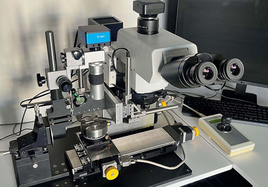
Fiber probe station with Olympus DIC microscope, side-view zoom camera and motorized stage
DIC microscope on the right, side-view camera and fiber probes on the left, one stage between them

The spot you inspect is the spot you probe

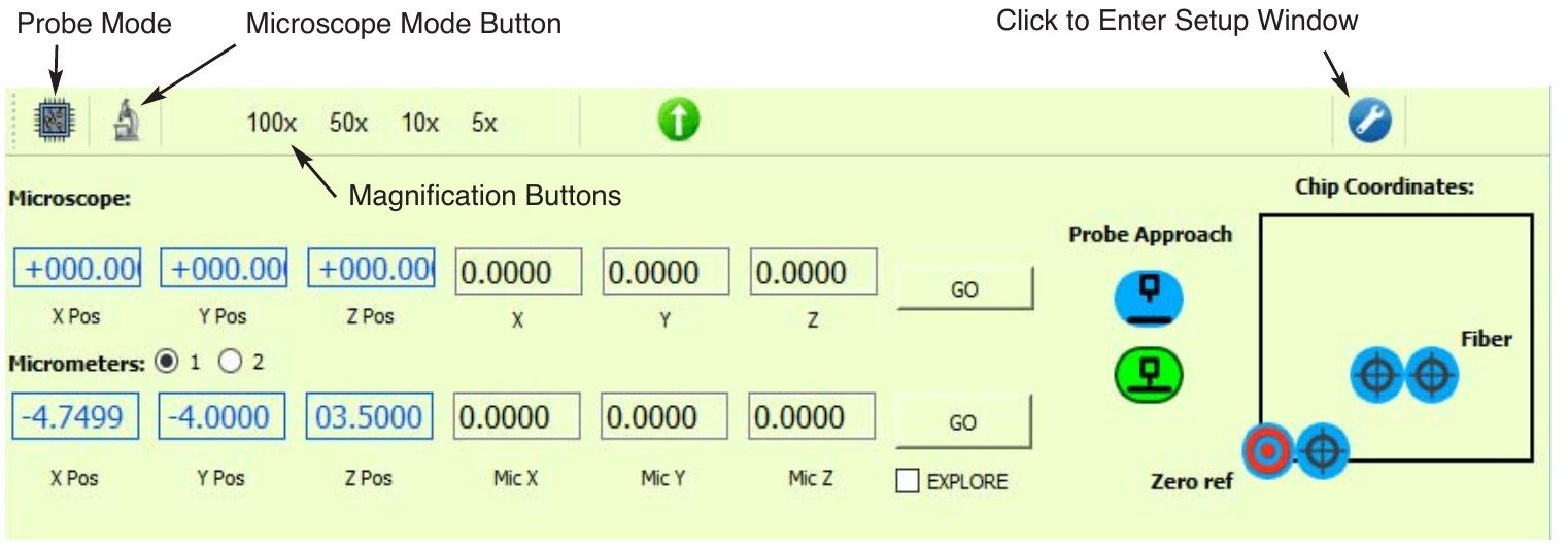
The microscope and the fiber probes share one lift platform and one reference point. Focusing the microscope on the chip sets the fiber height, and every position is remembered, so moving between inspecting and probing never means starting over.

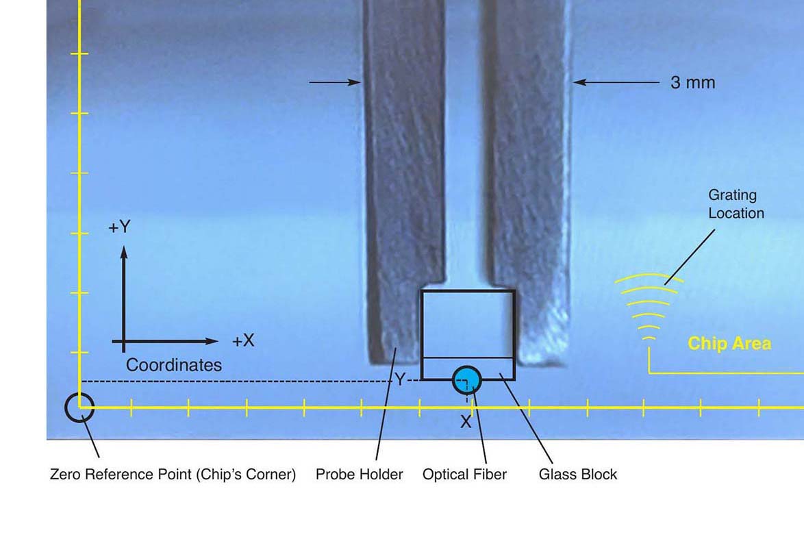
Set zero

Move the chip's corner under the laser fiber, using the side-view camera. This is the chip's zero coordinate.

Go to the coupler

Type in the coupler coordinates from your chip design. The main motors bring it under the probes.

Search

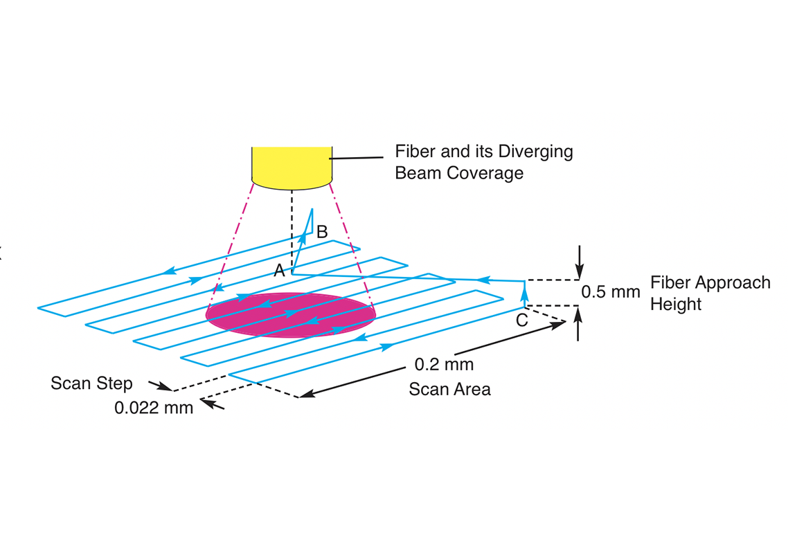
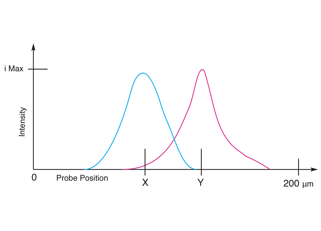
Motorized micrometers find the optimal coupling point automatically.

Inspect and return

One click lifts the probes and carries the chip under the microscope, focused on the same spot. One click brings it back.

The same find-and-transfer principle behind our patented AFM station, now applied to fiber-to-chip coupling.

Three configurations

Choose the imaging you need. Every configuration is built on the same base station.

Fixed Camera

Base + down-looking camera
Imaging
Camera looking down over the fibers
Chip size
Up to 40 × 90 mm
Best for
Teaching labs and routine measurements

Tiltable Camera

Base + side-view zoom camera
Imaging
8X zoom camera, tilts from vertical to horizontal
Chip size
Up to 40 × 90 mm
Best for
Safe approach, edge coupling, watching the fiber gap

The base station: dual motorized XYZ fiber probes, paired or fully independent · main motorized stage with joystick · vacuum chuck on a rotary stage · custom probe holders · Python control software with full source code included and licensed to the buyer.

Built for class 100 cleanrooms

Nine motorized stages at 0.1 µm resolution.

SamplesSilicon chips under 0.5 mm thick, on a vacuum chuck that holds wafers up to 100 mm diameter
Chip areaUp to 30 × 40 mm with the DIC microscope; up to 40 × 90 mm with camera-only configurations
MicroscopeOlympus DIC, brightfield and darkfield, motorized nosepiece
Objectives5X, 10X, 50X, 100X
Fiber probesTwo, each on motorized XYZ micrometers (Newport DC servo, USB), 12 mm travel per axis
Probe modesPaired fibers on one stage at any spacing, or two fully independent stages
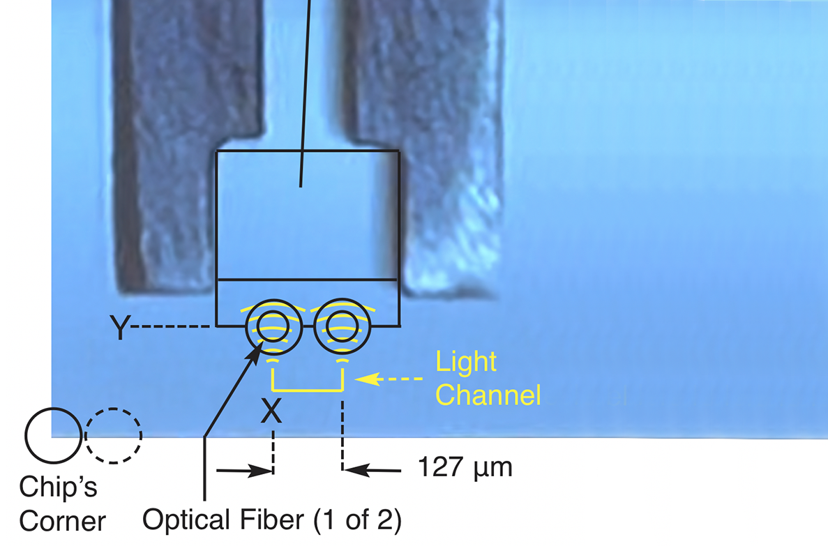
Fiber angleBuilt into the glass fiber block (8° face). Holders for standard fiber arrays cut at 8° or any angle on request
Side-view camera8X zoom, 38X–300X, tilts from vertical to horizontal
Cameras4K HD
SoftwarePython GUI, saved coordinates, automated alignment search. Full source code included and licensed to the buyer
Supplied by the userLaser source, detector or power meter, A/D interface. The software is ready for your detector.

A closer look

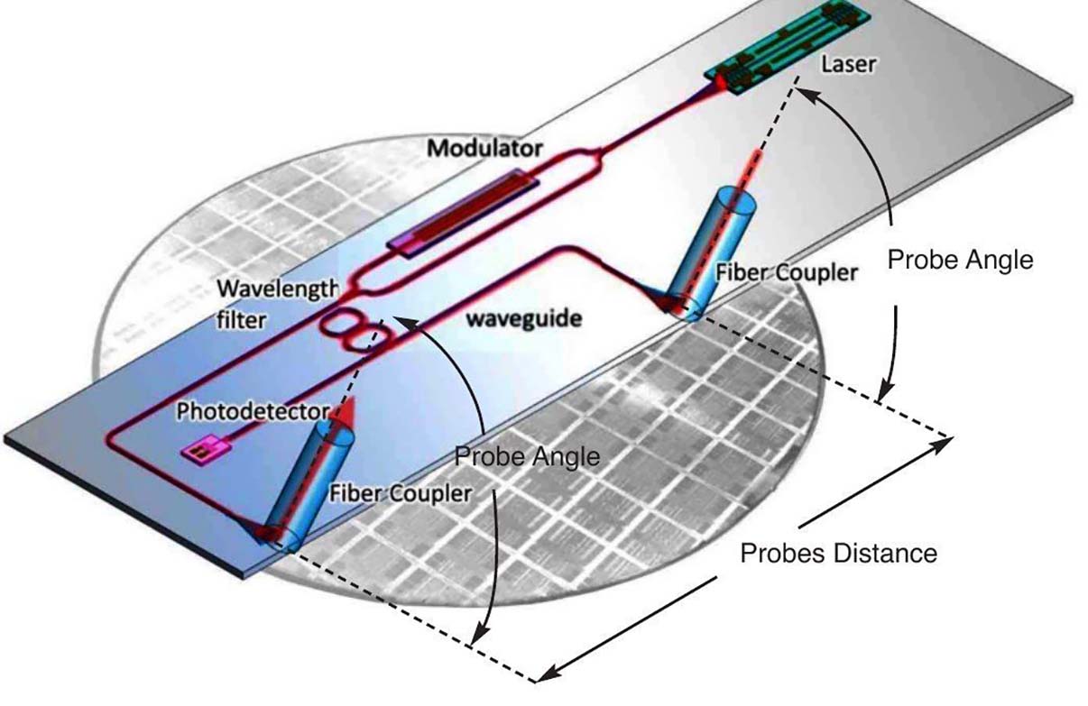
From the chip's circuit to the detector signal. Click any image to see it full size.

Made to fit your fiber arrays

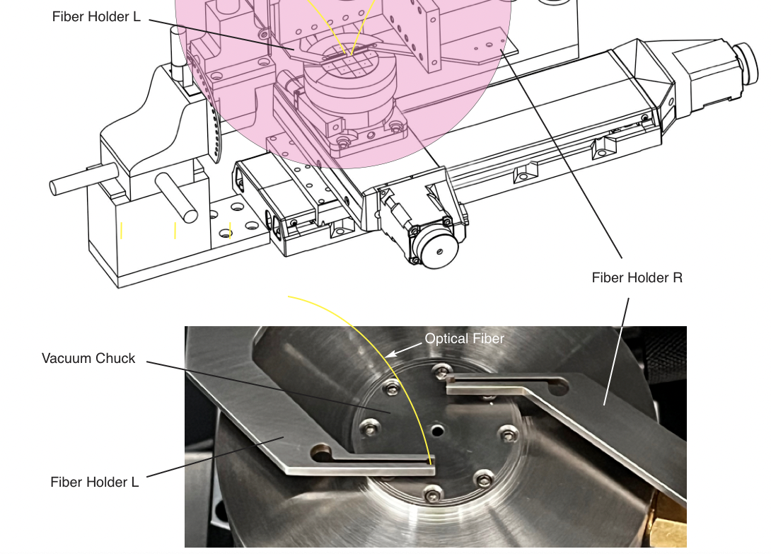
The probe angle is built into our glass fiber block, so the holder simply clamps it upright. No tilt stage, no goniometer.

Using standard V-groove fiber arrays? We cut holders by wire EDM to fit them, at 8° or any angle you specify. Send us your array's drawing.

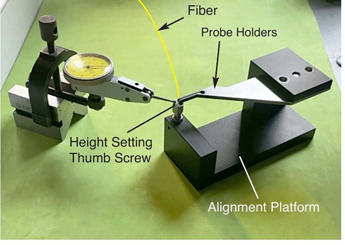
Holders swap with one thumb screw and relocate on registration pins.

Find it under the microscope. Move it under the fibers.

Built to order

Each station is built to order, with delivery within 4 weeks of order.

Request a quote, or request the full user's manual with setup, alignment and software details.